Create your CubeMars account

From industrial robotic arms to humanoid robots, upper-limb mobility is becoming an essential foundation for robots to perform complex operations. Whether it involves shoulder lifting, elbow flexion and extension, wrist rotation, or end-effector grasping, every movement relies on the precise coordination of multiple joints. To enable robots to achieve flexible movements similar to those of human arms, selecting the right joint drive modules is crucial.
Joint modules are the core power units of upper-limb robots, and their performance directly affects the robot's load capacity, movement speed, response accuracy, and overall structural design. To meet the drive requirements of different joints, motors must not only provide appropriate output torque and speed but also take into account the gear ratio, size, weight, control method, and continuous operating capability.
So, how should joint modules for upper-limb robots be selected? Which parameters should be considered for the shoulder, elbow, and wrist joints respectively? How should integrated drive solutions and quasi-direct-drive solutions be selected? From joint structures and key performance parameters to CubeMars AK, AKA, and AKE series power modules, this article explores drive solutions suitable for different robotic joints.
Upper-limb robots primarily simulate the movement structure of human arms and typically consist of components such as shoulder, elbow, and wrist joints. Different joints perform different movement tasks, resulting in significant differences in their drive capabilities and structural design requirements.
Shoulder Joint: Handling Large Loads and a Wide Range of Motion
The shoulder joint is typically responsible for movements such as arm lifting, forward and backward swinging, and rotation. It is one of the joints in an upper-limb robot with a relatively wide range of motion and complex load conditions.
When the robotic arm is raised or extended forward, the shoulder joint must not only drive the upper-arm structure but also withstand the torque generated by the forearm, wrist, end effector, and end load.
Therefore, when selecting a shoulder joint drive module, particular attention should be paid to output torque, continuous operating capability, structural strength, and heat dissipation performance. The weight of the drive unit must also be considered, as the shoulder motor itself becomes part of the robotic arm's load.
Elbow Joint: Balancing Output Torque and Motion Response
The elbow joint is primarily responsible for arm flexion and extension, and typically needs to drive the forearm and end effector to perform tasks such as grasping, handling, and positioning.
Compared with the shoulder joint, the elbow joint has a relatively concentrated range of motion, but its load changes with the posture of the robotic arm. For example, when the arm is fully extended, the moment arm between the end load and the elbow joint may increase, thereby increasing the required joint output torque.
Therefore, elbow joint selection requires comprehensive consideration of forearm length, end load, movement speed, and dynamic response. It should not be determined solely by the static load under a single posture.
Wrist Joint: Focusing on Lightweight Design and Control Accuracy
The wrist joint is primarily used to adjust the posture of the end effector. Common movements include pitching, deflection, and rotation.
Since the wrist joint is usually located at the end of the robotic arm, the weight of its drive unit will further affect the loads on the forearm and elbow joint. Therefore, in addition to meeting the required torque and speed, wrist joint selection should also consider motor size, weight, response speed, and control accuracy.
For robots that need to perform precision grasping, assembly, or human-robot interaction, the wrist joint must also have motion control capabilities that match the task requirements.
From the perspective of the overall structure, the joints of an upper-limb robot do not operate independently. Shoulder joint movement changes the positions of the elbow and wrist, while elbow joint movement also affects the torque exerted by the end load on other joints. Therefore, joint module selection needs to be evaluated in combination with the structure and movement patterns of the entire robotic arm.
The technical specifications of a joint module determine the types of movements a robot can perform. For upper-limb robots, output torque, speed, gear ratio, size and weight, control method, heat dissipation capability, and mechanical performance are all important factors to consider during the selection process.
1. Output Torque
Torque is an important parameter for measuring joint drive capability. It determines whether a joint can drive the arm structure and end load to perform specified movements.
In practical applications, rated torque and peak torque need to be distinguished. Rated torque is generally used to evaluate the motor's ability to provide continuous output under specified operating conditions, while peak torque is mainly used to handle acceleration, startup, or instantaneous load changes over short periods.
For example, when an upper-limb robot needs to maintain a raised-arm position for an extended period, particular attention should be paid to the joint module's continuous output capability. Whether the requirements are met should not be judged solely by peak torque.
When estimating torque, the static torque can first be calculated based on the load mass and moment arm length:
T=m\times g\times L
Where:
(L) represents the distance from the load's center of gravity to the joint's rotational axis.
For example, assume that the end of a robotic arm carries a 2 kg load, and the distance between the load's center of gravity and the joint's rotational axis is 0.25 m. The static torque is then:
T=2\times9.81\times0.25=4.905\ N\cdot m
This means that the joint needs to overcome a static load torque of at least approximately 4.905 N·m. In actual selection, factors such as the robotic arm's own weight, movement acceleration, friction losses, and dynamic impacts must also be considered, with a reasonable design margin reserved.
In addition, during dynamic movement, the joint must also overcome the torque generated by inertia. For rotational motion, an initial estimate can be made using the following relationship:
T_{\text{dynamic}}=J\times\alpha
Where (J) represents the moment of inertia and (\alpha) represents angular acceleration.
Therefore, the actual drive requirements of a joint generally need to be calculated by comprehensively considering static load torque, dynamic inertial torque, and other resistance forces.
2. Output Speed
Output speed determines the movement speed of upper-limb robot joints. Different joints have different movement frequencies and ranges of motion, so their speed requirements also vary.
For example, the shoulder joint needs to perform lifting and rotation over a relatively wide range, the elbow joint needs to perform flexion and extension according to task requirements, while the wrist joint may need to make frequent and subtle posture adjustments.
During selection, the required output speed should be determined based on the joint's maximum angular velocity, range of motion, and motion cycle. Attention should also be paid to the motor's actual speed performance under different load conditions.
It is important to note that a motor's no-load speed does not represent its actual operating speed. When a motor operates under load, its speed is affected by factors such as output torque, power supply conditions, and control strategies. Therefore, evaluation should be based on the product's speed-torque characteristics.
3. Gear Ratio
The gear ratio affects the output torque and speed of a joint module and is an important parameter in robotic joint drive design.
In a drive system combining a motor and a reduction mechanism, the reduction mechanism can decrease the output speed while increasing the output torque. Generally speaking, a higher gear ratio results in a more significant theoretical torque amplification effect at the output end, but the output speed decreases accordingly.
For upper-limb robots, the shoulder and elbow joints usually need to balance load capacity and movement speed. Therefore, an appropriate gear ratio should be selected according to actual movement requirements. For wrist joints, the decision should be made by considering movement accuracy, response speed, and available structural space.
A higher gear ratio is not necessarily better. An excessively high gear ratio may affect joint movement speed and dynamic response, and may also increase the complexity of the transmission structure. Therefore, a balance must be achieved between output torque, speed, and control performance.
4. Motor Size and Weight
Upper-limb robots usually need to integrate multiple joint drive units within limited structural space. Therefore, motor dimensions and weight directly affect the overall design of the robotic arm.
This is particularly important for wrist joints, where the weight of the drive unit becomes an additional load on the preceding joint. For example, a wrist motor not only needs to drive the end effector but also increases the loads on the forearm and elbow joint.
If the wrist drive unit is too heavy, it may further increase the torque requirements of the elbow and shoulder joints, affecting the movement efficiency of the entire robotic arm.
Therefore, while meeting torque and speed requirements, the size and weight of the joint module should be controlled as much as possible. A comprehensive evaluation should also be conducted based on the robotic arm's mounting structure, axial space, and connection method.
5. Control Methods and Feedback Capabilities
Upper-limb robots usually need to achieve coordinated movement across multiple joints. Therefore, the control methods and feedback capabilities of drive units are equally important.
In practical applications, common control requirements include position control, speed control, and torque control. Position control is mainly used to achieve joint angle positioning, speed control is used to adjust joint movement speed, and torque control helps achieve load adjustment and compliant motion.
In addition, feedback devices such as encoders can help the control system obtain the operating status of the motor or joint, providing data support for closed-loop control.
In multi-joint systems, attention should also be paid to the drive's communication interfaces, control protocols, parameter configuration, and multi-motor coordinated control capabilities. When selecting joint modules, it is necessary to confirm whether their control interfaces are compatible with the robot's main control system.
6. Heat Dissipation and Continuous Operating Performance
During long-term operation, upper-limb robot joint motors may continuously bear loads and generate heat. If heat dissipation is insufficient, the motor temperature may gradually rise, affecting its continuous output capability and the operating stability of the system.
Therefore, during selection, it is necessary not only to consider peak torque but also to evaluate continuous operating capability under rated conditions and the heat dissipation conditions of the motor within the actual mounting structure.
For upper-limb robots that need to maintain postures for extended periods, start frequently, or perform continuous movements, the motor's thermal performance should be evaluated in combination with the duty cycle, load variations, and installation environment.
7. Mechanical Performance and Transmission Accuracy
In addition to electrical parameters, the mechanical performance of a joint module also affects robot movement performance.
For upper-limb robots that require precise positioning, transmission backlash, torsional stiffness, and structural strength are all worth considering. Transmission backlash may affect positional accuracy when a joint moves in the reverse direction, while torsional stiffness affects the deformation of a joint under load.
If a robot needs to perform precision operations, repetitive positioning, or human-robot collaboration tasks, the mechanical performance of the drive unit should be evaluated according to the actual accuracy requirements.
After understanding the various parameters, the next step is to match the drive modules with specific joint positions. Different joints in upper-limb robots have different loads, ranges of motion, and installation conditions. Therefore, targeted matching strategies should be adopted.
If the robot needs to achieve multi-degree-of-freedom shoulder movement, the spatial arrangement and coordinated control of multiple drive units should also be considered. The drive modules must not only meet the power requirements of individual joints but also adapt to the overall mechanical structure of the shoulder.
During selection, the required joint torque should be calculated based on the actual load, and the module's output capability at different speeds should be evaluated. For robots that frequently perform grasping, handling, and operating tasks, attention should also be paid to the dynamic response and transmission stability of the drive system.
The wrist joint is usually installed at the end of the upper limb, and its weight directly affects end-load capacity and motion inertia. Therefore, wrist drive modules should keep their size and weight as low as possible while ensuring that their output capabilities meet requirements.
It is important to note that the drive requirements of the shoulder, elbow, and wrist joints are not fixed. Even at the same joint position, significant differences may exist depending on the robot structure, load, and movement task. Actual selection should still be based on joint dynamics calculations and the test results of the complete robot.
Upper-limb robot joint drive solutions can generally be divided into two types: integrated drive solutions and separate drive solutions. Each has its own characteristics in terms of structural design, system integration, and maintenance methods.
A separate drive solution usually consists of individual components such as a motor, gearbox, driver, and encoder. Developers can select different components according to actual requirements and configure them independently. This solution offers a high degree of design flexibility and is suitable for robot projects with special structural requirements or those requiring deeply customized drive systems.
However, a separate solution also means that more mechanical connections, electrical connections, and control interfaces need to be handled. Matching and debugging multiple components may increase system integration workload and occupy more installation space.
Integrated joint modules combine components such as the motor, reduction mechanism, driver, and feedback elements into a relatively compact structure. This helps reduce external connections and system wiring while lowering the complexity of mechanical structural design and installation.
For upper-limb robots that need to integrate multiple joint drive units, an integrated solution can help simplify the system structure and improve overall integration efficiency. However, its actual suitability still needs to be determined based on output performance, mounting interfaces, control protocols, and heat dissipation conditions.
| Comparison Criteria | Separate Drive Solution | Integrated Joint Module |
Structural Composition | Motors, gearboxes, drivers, and other components configured independently | Multiple drive components integrated into a single module |
Design Flexibility | More flexible component selection and configuration | Requires selection based on existing product specifications |
Installation Space | Usually requires installation space for multiple components | Relatively compact structure |
System Integration | Requires handling connections between multiple components | Helps reduce external connections |
Debugging Work | Related components need to be configured and debugged separately | Can be configured according to the control method of the integrated driver |
Suitable Applications | Highly customized drive systems | Robots requiring compact structures and high integration efficiency |
Therefore, if a project has extensive customization requirements and the development team wants to configure the motor, gearbox, and driver independently, a separate solution can be considered. If the project places greater emphasis on structural compactness, installation efficiency, and drive system integration, integrated joint modules can be evaluated as a priority.
Different types of upper-limb robots have different design priorities when it comes to joint drives. Humanoid robots need to achieve movements similar to those of human arms through multiple joints, emphasizing power output, dynamic response, and multi-joint coordination. Exoskeleton robots, on the other hand, need to work in conjunction with human movement, placing greater emphasis on wearable structures, human-robot coordination, and the overall assisted-drive experience.
To address the requirements of these two types of applications, CubeMars offers the AK series and AKE series products, which can serve as key product selection directions for humanoid robot and exoskeleton robot joint drive solutions, respectively.
Humanoid Robots: CubeMars AK Series
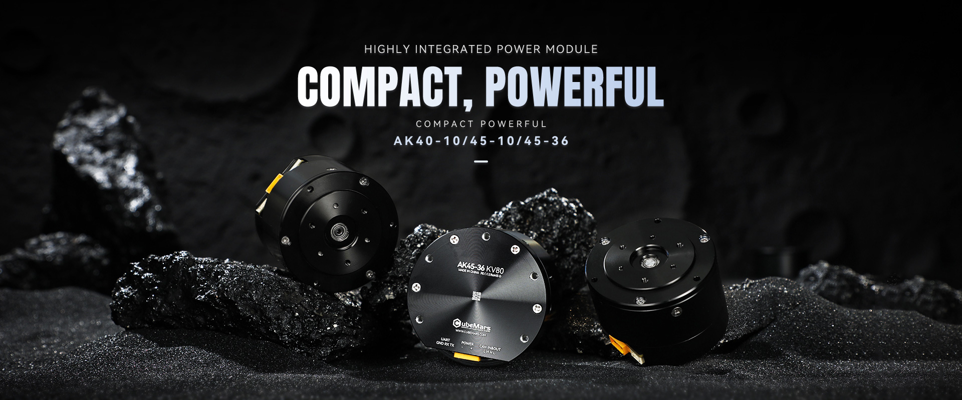
The upper limbs of humanoid robots typically contain multiple moving joints, including the shoulders, elbows, and wrists. These joints need to perform movements such as arm lifting, elbow flexion, rotation, grasping, and object manipulation. Different joints need to remain coordinated, so the drive system must not only provide sufficient power but also take structural integration and motion control into account.
CubeMars AK Series products are integrated robotic actuators and can serve as a key selection direction for humanoid robot joint drives. This series integrates functions such as the motor, reduction mechanism, and drive control into the joint module, helping simplify the mechanical and electrical integration of the drive system.
In specific applications, different AK series models can be selected according to the load requirements of the shoulder, elbow, and wrist joints. For shoulder joints, the module's continuous torque and peak torque should be evaluated carefully. For elbow joints, matching should be based on forearm loads and movement speed. For wrist joints, greater attention should be paid to product dimensions, weight, and end-motion requirements.
In addition to the power performance of individual joints, coordination between multiple AK series drive units and the robot control system must also be considered, including communication interfaces, control protocols, encoder feedback, and multi-joint coordinated control.
Therefore, the application of the AK series in humanoid robots should be based on the specific robot structure, joint degrees of freedom, load conditions, and control system when selecting models, rather than simply using the same model for all joints.
Exoskeleton Robots: CubeMars AKE Series
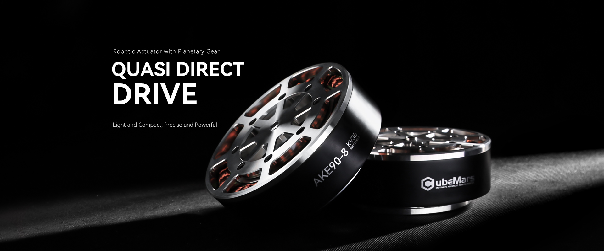
The biggest difference between exoskeleton robots and humanoid robots is that their drive systems need to move together with the human body. Upper-limb exoskeletons are typically used to assist the shoulders, elbows, or wrists in performing movements such as lifting and flexion and extension, helping wearers reduce part of their movement burden or complete specific assistance tasks.
Compared with traditional robotic joints, exoskeleton joint design needs to consider not only drive capability but also human-robot motion coordination, joint-axis alignment, wearing comfort, and overall system weight. The drive module needs to provide assistance while minimizing restrictions on the body's natural movements.
CubeMars AKE Series products are quasi-direct-drive (QDD) motors and can serve as a key selection direction for exoskeleton robot joint drives. Through a transmission design with a relatively low gear ratio, the quasi-direct-drive design balances output capability, dynamic response, and backdrivability, making it suitable for applications that require attention to human-robot interaction and compliant motion.
For upper-limb exoskeleton projects, different AKE series models can be evaluated in terms of output torque, speed, dimensions, and weight according to the assistance requirements of joints such as the shoulder and elbow.
In actual design, shoulder assistance joints need to determine drive capability based on the wearer's arm weight, assisted load, and range of motion. Elbow assistance joints need to be matched according to forearm weight, end load, and target movement speed.
In addition, exoskeleton robots need to fully consider human-robot interaction safety. The drive system should work together with sensors, control algorithms, and mechanical limit structures so that the assistive output can be adjusted according to human movements and actual requirements, avoiding any impact on the wearing experience caused by mismatched drive responses.
Therefore, AKE series selection for exoskeleton robots should focus on wearable structure, assistive torque, backdrivability, and continuous operating capability, and should be verified in combination with the specific application scenario.
AK Series vs. AKE Series: How to Choose According to Application Scenarios?
Both the AK series and AKE series can be used for robotic joint drives, but they differ in product structure and drive design concepts. The AK series adopts an integrated actuator design, while the AKE series adopts a quasi-direct-drive (QDD) design. For upper-limb robot projects, selection should be based on the robot type, joint tasks, and system integration requirements.
| Comparison Criteria | CubeMars AK Series | CubeMars AKE Series |
| Product Positioning | Integrated Robotic Actuator | Quasi-Direct-Drive (QDD) Motor |
| Structural Characteristics | Integrates the motor, reduction mechanism, drive control, and other functions | Low gear-ratio transmission design, balancing power output and backdrivability |
| Main Recommended Application in This Article | Humanoid Robots | Exoskeleton Robots |
| Drive Design Priorities | Joint power output, system integration, and multi-joint coordination | Dynamic response, backdrivability, and compliant interaction |
| Selection Considerations | Rated torque, peak torque, speed, installation space, and control method | Assistive torque, backdrivability, product weight, and wearable adaptation |
| Typical Application Considerations | Robotic joints such as the shoulder, elbow, and wrist | Human-motion assistance joints such as the shoulder and elbow |
In terms of product structure, the CubeMars AK series adopts a highly integrated design, making it suitable for humanoid robot projects that aim to simplify joint drive systems and reduce the integration complexity of peripheral components. For robots requiring coordinated operation across multiple joints, suitable AK series models can be selected according to the loads and movement requirements of each joint.
The AKE series adopts a quasi-direct-drive design. Its low gear-ratio transmission helps improve the backdrivability and dynamic response of the drive system. In exoskeleton robots, these characteristics help designers evaluate the coordination between drive output and human movement.
Therefore, for humanoid robot projects, the CubeMars AK series can be evaluated as a priority; for upper-limb exoskeleton projects, the CubeMars AKE series can be evaluated as a priority. It should be noted that these are product recommendation directions for the two types of applications discussed in this article. This does not mean that the two series can only be used in their corresponding scenarios. The final decision should still be based on the performance specifications of specific models, mechanical structures, control requirements, and actual operating conditions.
To improve selection efficiency, the process can be carried out in the following order, starting with application requirements and ending with product verification.
First, determine the primary purpose of the upper-limb robot, such as industrial grasping, material handling, rehabilitation training, scientific research experiments, or human-robot collaboration. Different application scenarios have different requirements for load capacity, movement speed, control accuracy, and safety performance.
Based on the robotic arm structure, determine the movement directions, ranges of motion, maximum angular velocities, and motion cycles of the shoulder, elbow, and wrist joints. At the same time, clarify whether each joint needs to maintain a posture for an extended period and whether frequent starts and stops or rapid acceleration and deceleration are involved.
Calculate the static and dynamic torque required by different joints based on the robotic arm's own weight, end load, center-of-gravity positions of various components, and movement postures. For complex movement tasks, further analysis should be conducted in combination with a dynamic model.
Step 4: Determine Motor and Reduction Mechanism Parameters
Based on joint torque and speed requirements, select suitable motors and gear ratios. In addition to rated torque and peak torque, the motor's output capability within the actual operating range also needs to be evaluated.
Incorporate the candidate drive modules into the mechanical structure design and check installation space, connection interfaces, axial length, cable routing, and maintenance space. At the same time, confirm communication compatibility between the driver and the robot control system.
After completing the preliminary selection, prototype testing should be conducted to verify the actual movement performance of the joints. Key tests should include load capacity, movement speed, positioning accuracy, temperature rise, continuous operating capability, and multi-joint coordination. The motor model or transmission solution should then be adjusted according to the test results.
Peak torque usually refers to the output capability over a short period and cannot directly represent the load that a motor can withstand over the long term. For upper-limb robots that need to maintain postures continuously or perform continuous movements, rated torque, duty cycle, and temperature rise performance should be evaluated carefully.
The upper arm, forearm, connecting components, and end effector all generate loads on the joints. Particularly when the arm is extended, the gravity of structural components may generate considerable torque. Therefore, selection should not be based solely on the mass of the end load.
A higher gear ratio helps increase output torque, but it also reduces output speed and may affect the dynamic response of the system. An appropriate gear ratio needs to be selected according to actual movement speed and load requirements.
The weight of a drive unit at one joint may become an additional load on the preceding joint. Wrist motors are particularly important in this regard, as their weight affects the drive requirements of the forearm and elbow joint. Therefore, selection needs to be evaluated from the perspective of the entire robotic arm.
Even if a motor meets the torque and speed requirements, incompatible communication interfaces, control protocols, or feedback methods may increase development and debugging difficulties. Therefore, the compatibility between the drive unit and the control system should be confirmed at the initial stage of selection.
The AK, AKA, and AKE series include different models and specifications. Their suitability for shoulder, elbow, or wrist joints cannot be determined solely by their series names. The correct approach is to select products based on the technical specifications, mechanical structures, and actual loads of specific models.
Selecting joint modules for upper-limb robots is not simply a matter of comparing motor torque, speed, or dimensions. It is a process that requires comprehensive consideration of mechanical structure, load capacity, motion performance, and system integration. The shoulder, elbow, and wrist joints perform different movement tasks, and their drive requirements also differ significantly. Only by fully understanding the operating characteristics of each joint can a drive solution that matches the overall robot design be selected.
First, it is necessary to start with the robot's actual application scenario and define the joint loads, range of motion, maximum speed, and duty cycle. For shoulder and elbow joints, particular attention should be paid to the robotic arm's own weight, end load, and the torque generated under different movement postures. For wrist joints, in addition to meeting drive capability requirements, particular attention should be paid to motor size, weight, and control accuracy. At the same time, the load transfer relationships between different joints must also be considered to avoid increasing the burden on other joints due to an excessively heavy individual drive unit.
Second, the key performance of joint modules should be evaluated according to specific operating conditions. Rated torque determines the continuous output capability of the drive unit, while peak torque is used to evaluate the maximum output requirements over short periods. Output speed and gear ratio affect joint movement speed and power performance. In addition, factors such as control methods, encoder feedback, heat dissipation capability, transmission backlash, and torsional stiffness also affect the robot's stability, response speed, and movement accuracy during actual operation. Therefore, motor suitability cannot be judged based on a single parameter alone. A comprehensive comparison must be made in combination with the complete operating conditions.
In terms of drive solutions, integrated joint modules combine multiple drive components into a relatively compact structure, helping reduce external connections and system integration workload. Separate drive solutions offer greater configuration flexibility and are more suitable for projects that require independent design and customization of drive systems. Developers can choose a more appropriate solution according to the mechanical structure, installation space, control requirements, and development resources.
For teams developing upper-limb robots, robotic arms, and multi-joint robotic systems, the CubeMars AK, AKA, and AKE series can serve as product references for joint drive selection. Different series and specific models vary in structural design, transmission solutions, and performance specifications: the AK and AKA series can be evaluated according to the output capabilities and mounting specifications of specific models, while the AKE series can be considered in combination with the dynamic response and torque control requirements of quasi-direct-drive solutions. In practical applications, products should be selected according to the different requirements of shoulder, elbow, and wrist joints, with reference to parameters such as rated torque, peak torque, speed, gear ratio, dimensions, weight, and control interfaces in the product datasheets.
Finally, theoretical calculations are only the starting point for selection. Actual testing is equally important. After completing the preliminary model matching, prototype verification is still required to evaluate joint movement performance under real loads. Key aspects to check include continuous output capability, dynamic response, temperature rise, positioning accuracy, and multi-joint coordinated control performance. The drive configuration should then be further optimized according to the test results.
Overall, appropriate upper-limb robot joint module selection requires a balance between output performance, structural dimensions, overall system weight, control capabilities, and system integration. Selecting suitable drive products according to the actual requirements of different joints can not only improve the movement performance of the robotic arm but also help reduce system development and integration difficulties, laying a solid foundation for subsequent functional expansion and robot performance optimization.